The first test circuit and my findings, some data at last!
First test results
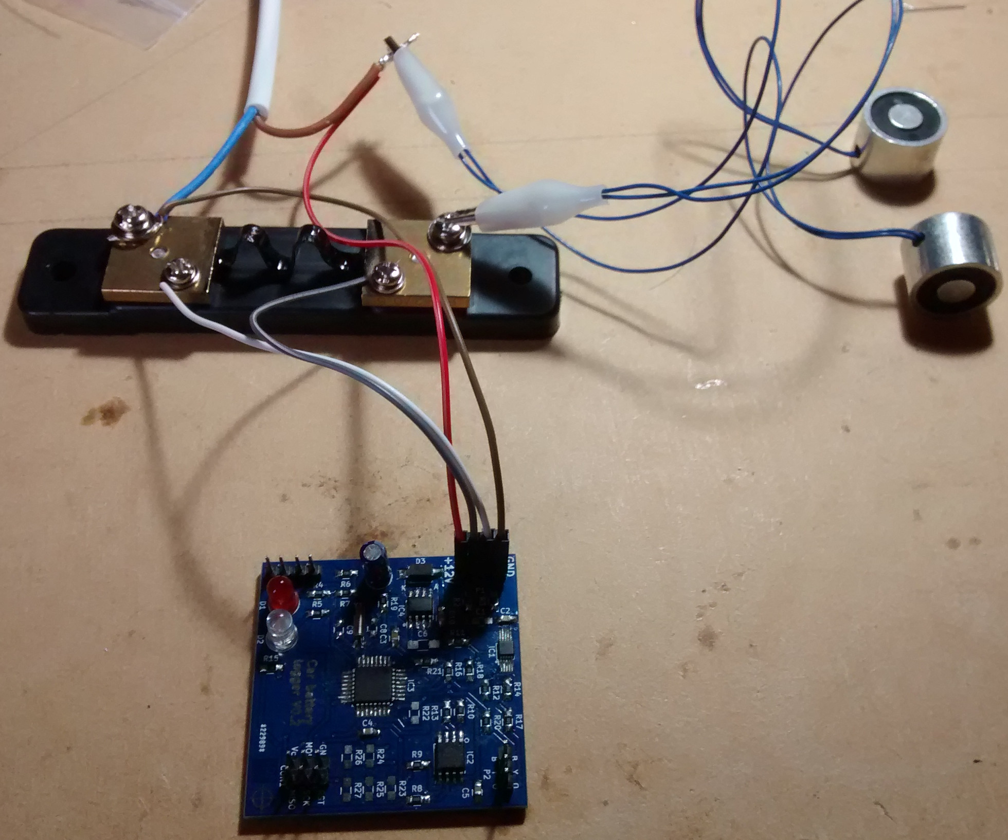
I wired the 10A/75mV shunt and a couple of electromagnets to my bench power supply. The positive side of the supply goes to he electromagnets and the circuit, the negative to the shunt and the circuit. The other side of the electromagnet goes to the shunt. The two sense wires go from the shunt to the circuit.
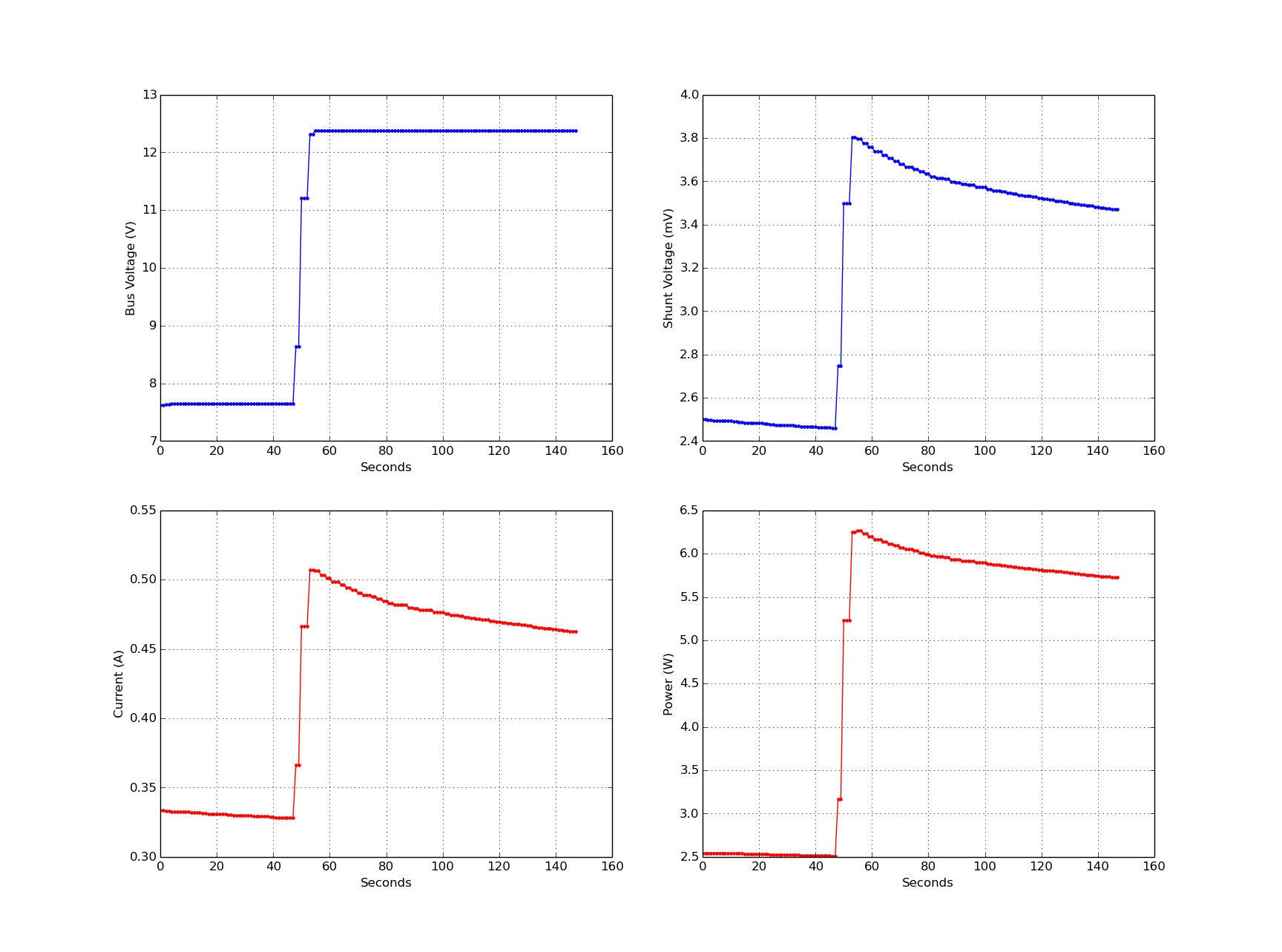
Below you can see the measurements made by the circuit, the power supply voltage started at about 7.8V then I turned it up a bit to about 12.4V. I thought it was pretty cool to see the power usage of the coils go down as the coils heated up due to this
The case
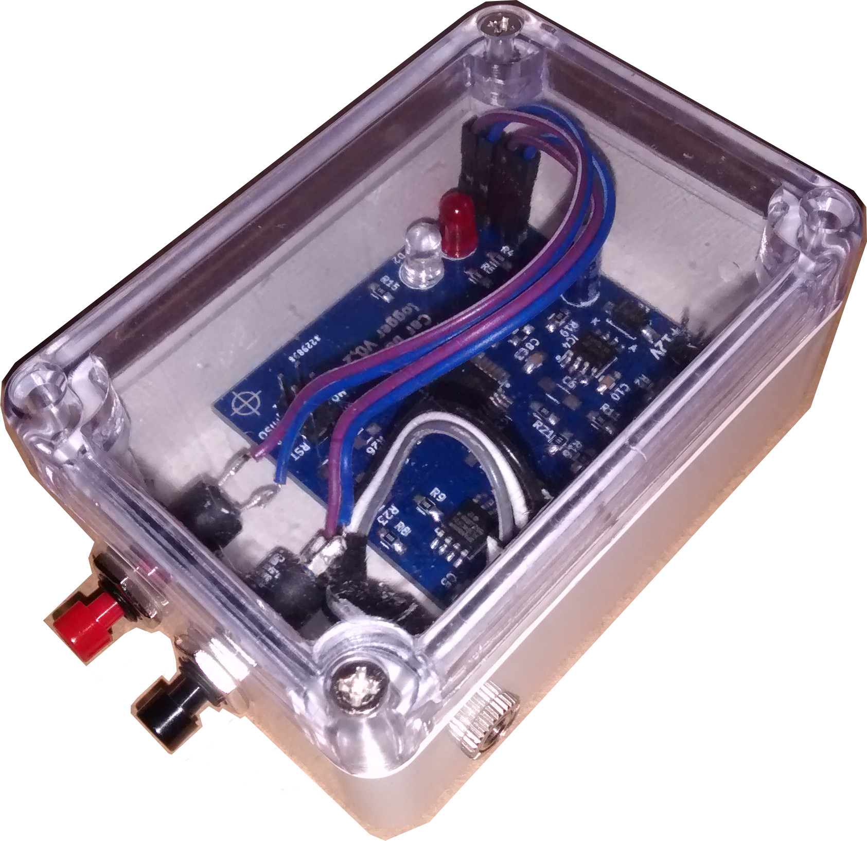
I found a cheap off the shelf case to put the board in when it’s mounted in the car. At first I was going to mount the LED’s to the case, but once I found a case with a clear top I realised that was pointless. I drilled a few holes for the panel mounted buttons and the audio jack that connects the serial. There is a hole in the other end of the case that I will put a rubber grommet into and feed the wires through to attach to the external shunt in the car.
Problems found while testing
Reset problem
Once I had started using v0.1 of the board it seemed to be running fine for days while I was writing code for it, then I saw the occasional rest, most annoying. I thought perhaps it had something to do with the clearance around pads and the copper pours (mentioned in earlier blog post). I didn’t have any problems with the prototype which I had also run for several days without a problem. Interestingly the reset seemed to correlate with the rise in ambient temperature in the room the board was in. Temperature changes effect many things in circuits due to the change in resistance in components, with high speed signals it can have a significant impact on their timing, but I had a feeling something was out of spec and was only working by chance, time to take a good look at all of the data-sheets for every component.
Problem with the crystal on new board
Once i’d built up the second board (v0.2) I found the timer derived from the 32.768KHz crystal wasn’t running for some reason, interestingly the atmega328p on the new board was from a different batch than the previous board that had the occasional reset problem.
The datasheet for the atmega328p has the following table in it for the maximum ESR recommendation for 32.768KHz crystal:
| Crystal CL (pF) | Max ESR (Kohm) |
|---|---|
| 6.5 | 75 |
| 9.0 | 65 |
| 12.5 | 30 |
From this table you can see as the load capacitance of the crystal goes up the maximum ESR that can be handled by the drive circuitry in the atmega328p goes down.
The first crystal I had chosen (used on the board that has shown reset problems) was this one CFS206-32.768-KDZF-UB it has a load capacitance of 12.5pF and ESR of 35Kohm which is 5Kohm higher than the maximum allowed. I think this was causing the reset problem.
I changed the crystal for this one CFS206-32.768-KDZB-UB which has a load capacitance of 6.0pF and ESR of 35Kohm which is well inside the requirements of the atmega328p. Since this component change I haven’t seen any more unexpected resets.
Some more information about the land rover
While working on this project I heard the car making a faint clicking noise when walking past it so I decided to investigate. Before we bought the car it had the rear air bag suspension replaced with coil springs, at the side of the car is a box containing a compressor for these bags and some electronic valves. Most of the electrical connections to this unit had been disconnected, all but one which was the one that was clicking, so I completed the job and removed the rest of the unit. The battery draining problem has now gone away. I didn’t get around to logging the power consumption on the land rover in the end, but I do have a nice new shiny toy to play with :).