Overview of the project
I wanted a remote controlled LED matrix to have a play with and I had some addressable LED strips, I also had a few raspberry Pi’s which are any easy way to get connectivity to a project when it’s running Linux. The only drawback of a SBC (single board computer) running Linux is that it’s hard to get very tight timings on the IO port, I thought to make the project easy I would do the real time activities on a micro controller and connect that to the Pi.
All of the code for this project can be found on github here
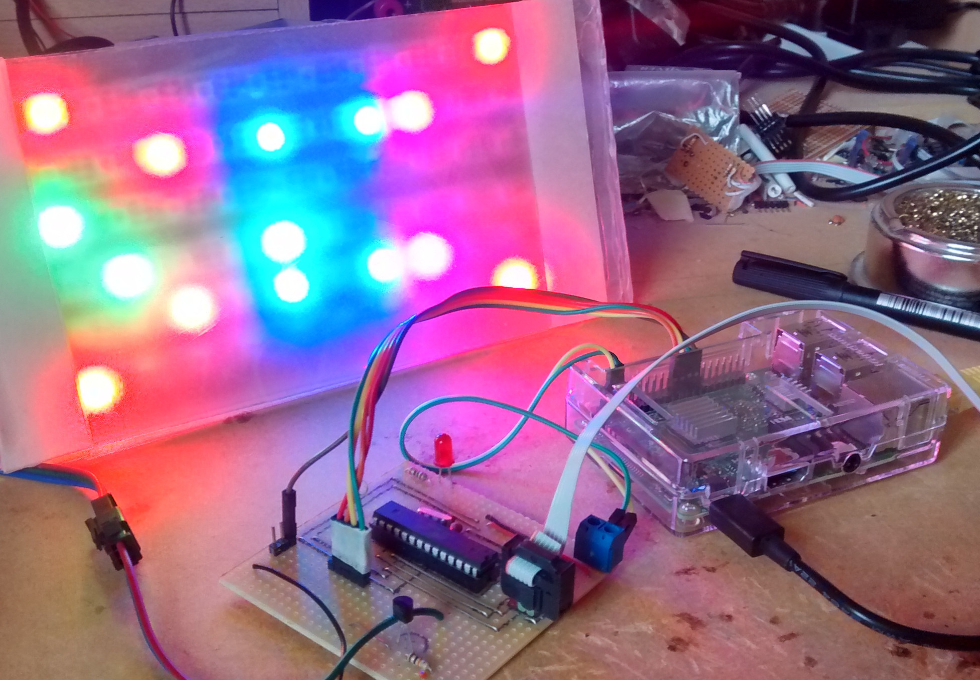
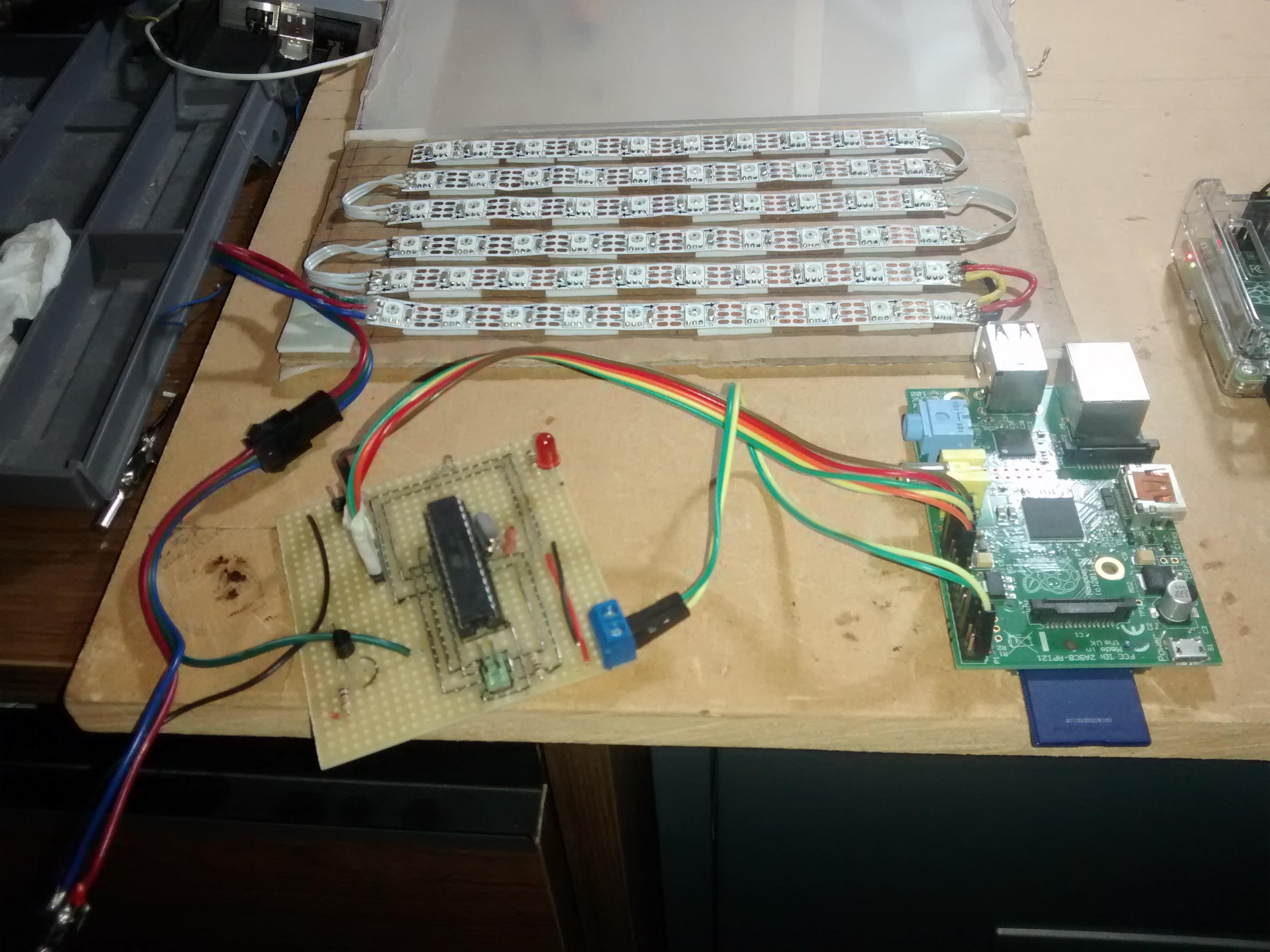
The resulting project looked like this:
Implementation decisions
I know there are ways of controlling these LED strips directly from a Raspberry Pi using DMA, but I wanted to write as much of this project as possible from scratch and I wanted to make a SPI slave device using the Atmega328p.
Hardware
Here is a simple sketch of the hardware setup:
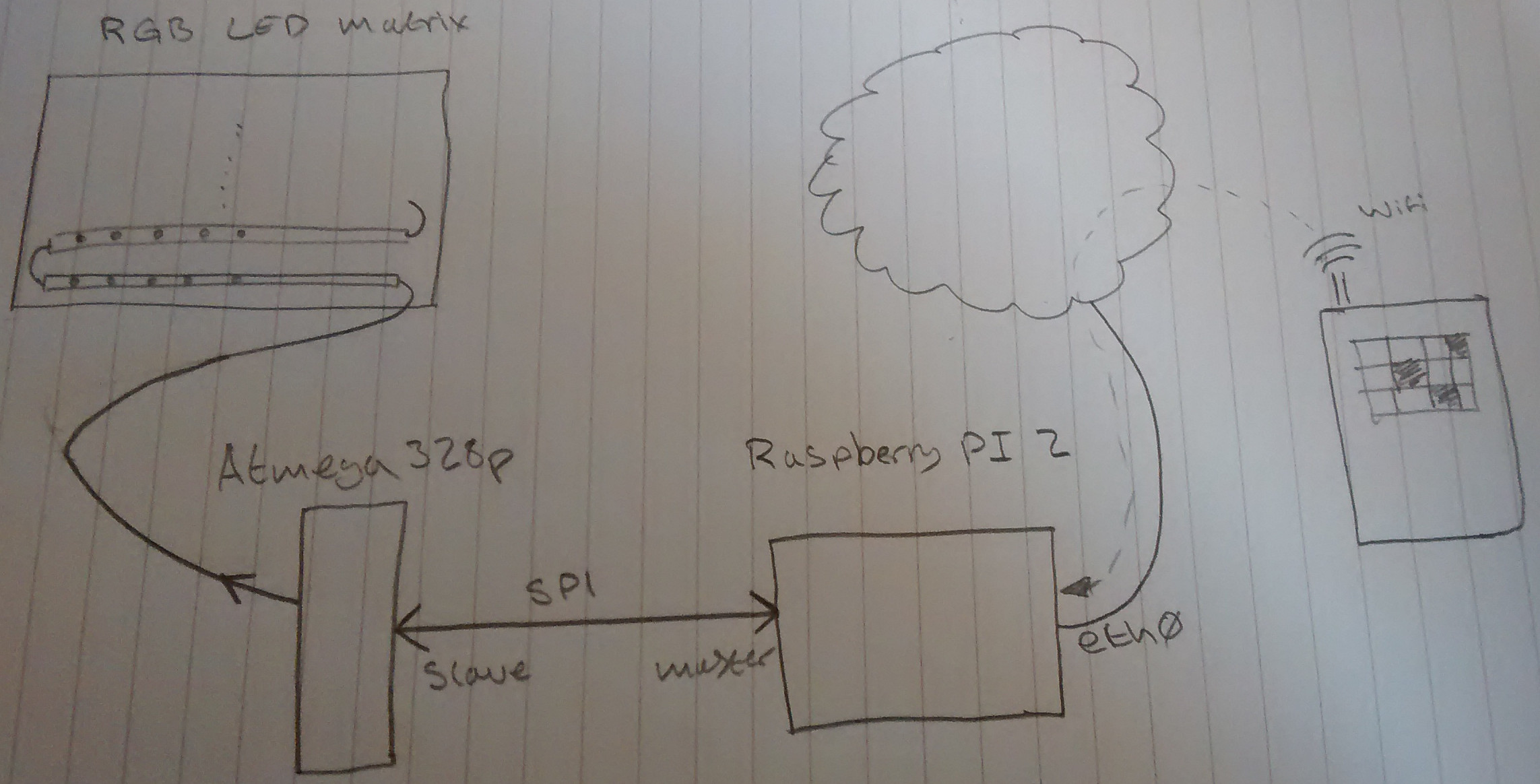 The LED strip can draw quite a lot of current so it has a separate power supply (5V) and the Atmega is powered from the raspberry Pi (3V), due to this there should really be some signal buffering between the Atmega and the LED strip, but it seems to work fine, so that’s fine for this project.
The LED strip is connected directly to the Atmega and the SPI bus is connected directly to the raspberry Pi which has an ethernet connection to my home network.
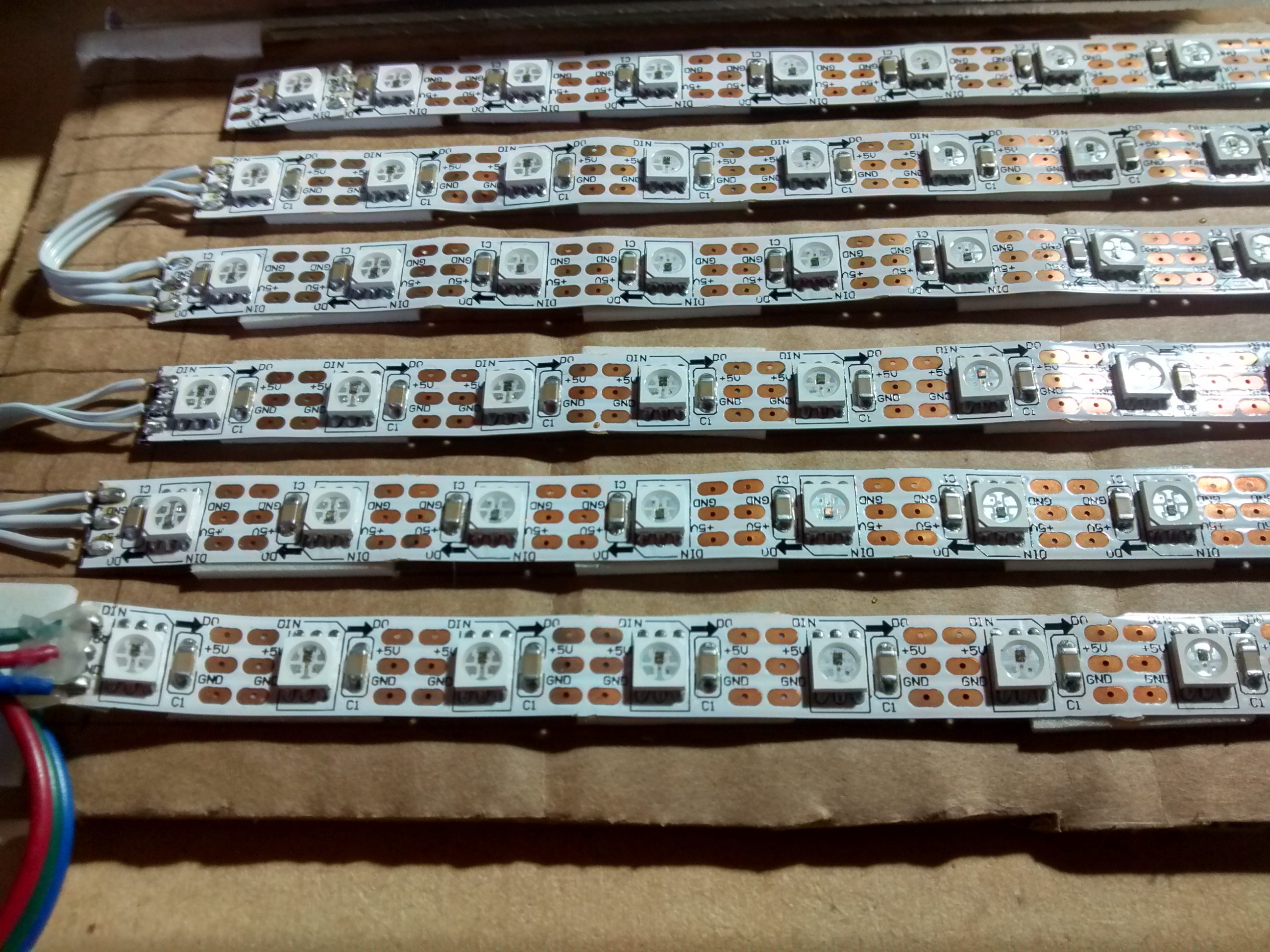
Here’s how I wired up the LED strip to form a matrix:
Here’s the circuit all wired up:
It’s work noting to program the AVR the SPI connection to the raspberry Pi must be disconnected as the signals interfere with each other.
WS2812 timining
The WS2812 has some pretty tight timing requirements, a copy of the datasheet can be found here
Below is the section from the data sheet that we are interested in:
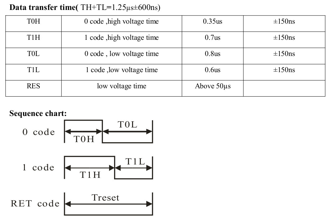 So, to send the code for a 0 the line must be high for 350nS and then low for 800nS and to send the code for a 1 the line must be high for 700nS and then low for 600nS. 24 bits of data must be sent to each LED, 8 bits of green, then red and then blue. To complete the transfer of data a delay of 50uS must be given, if there is no delay then the data will be shifted onto the next LED in the strip i.e to get data to the last LED on the strip data must be sent to all of the LEDs on the strip.
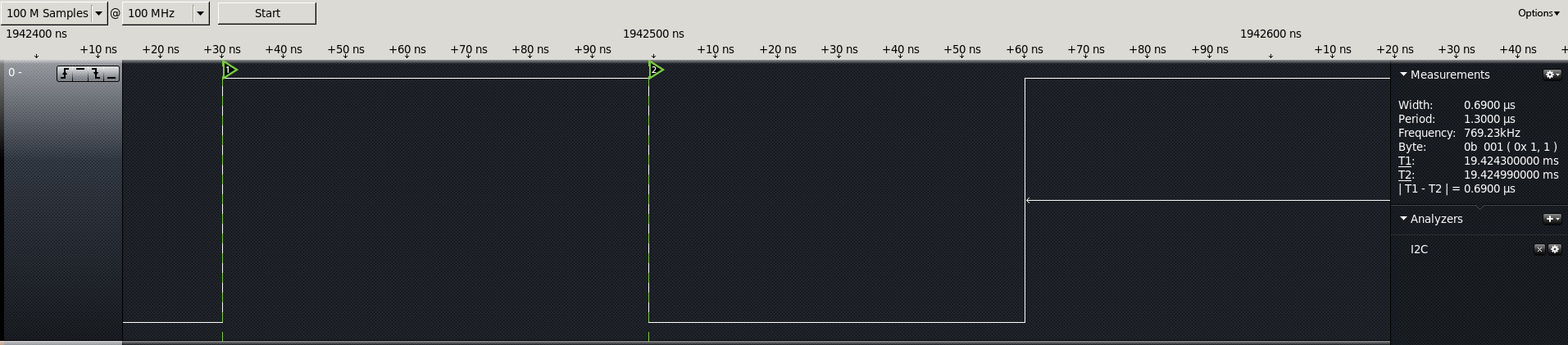
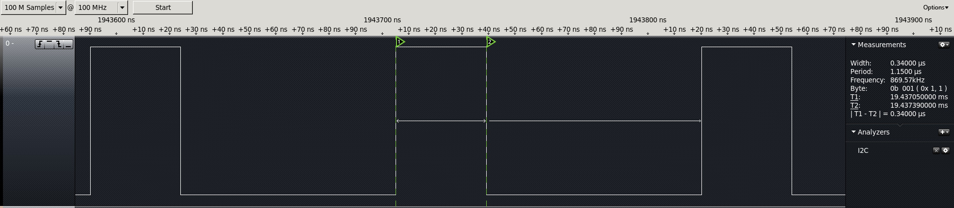
Here are the measured timings generated by my code on github. In the first diagram the “1” marker is at the start of the high and marker “2” is at the end of the high, on the right of the diagram “|T1 - T2|” measures the difference between those two markers as 340nS (close enough to 350nS). The period of the signal is 1150nS, 1150-340 = 810 (close enough to 800nS).
 Here are the same measurements done for a code of one.