Here’s my first look at a STM32 processor where I look at how to setup the build environment and start exercising the peripherals.
Introduction
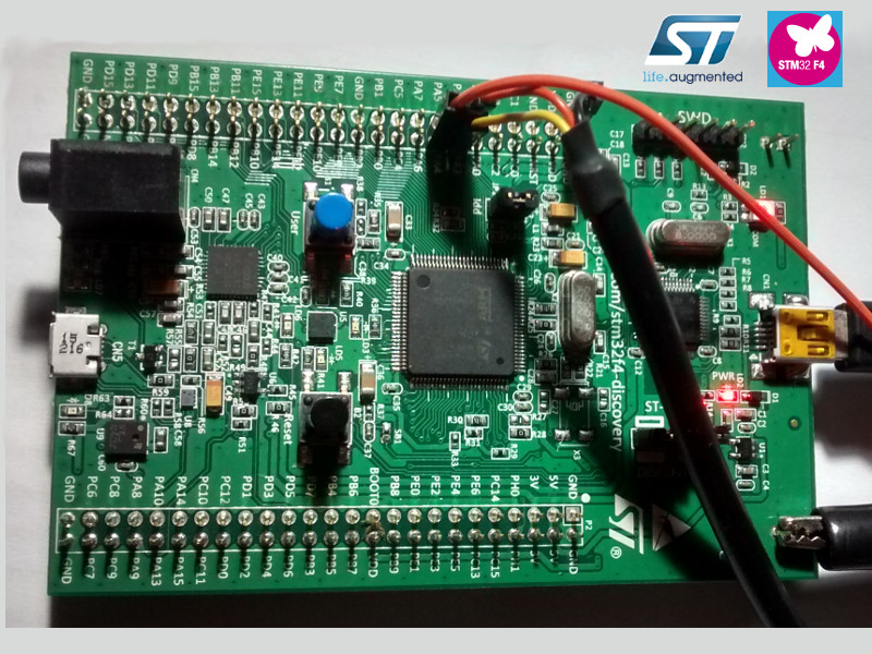
My first dev board I am going to look at is the STM32 F4 Discovery, it’s a very cheap and capable board that includes everything required to program code into the main processor. All of the code I refer to in this post is available on my github page github_stm32f4_first_look. All of the following setup was done on a machine running Ubuntu.
Setting up the environment
Before writing any code the environment needs to be setup, a tool called stlink can be used for flashing the code and gcc can be used for compiling it. My Makefile handles compiling and flash code as soon as two variables have been set (TOOL_BASE and STLINK).
stlink
I use the stlink tool to flash code onto the board, it can be found here, and this is how to install it:
$> git clone https://github.com/texane/stlink.git
$> sudo apt-get install libusb-1.0-0-dev
$> cmake -DCMAKE_BUILD_TYPE=Debug
$> make -j 4
Compiling
First toolchain
This is how I installed the first toolchain used for compiling:
$> wget 'https://launchpad.net/gcc-arm-embedded/5.0/5-2016-q3-update/+download/gcc-arm-none-eabi-5_4-2016q3-20160926-linux.tar.bz2'
$> tar xjvf gcc-arm-none-eabi-5_4-2016q3-20160926-linux.tar.bz2
Second toolchain
The first toolchain was working great until I started to use floats in my code, after looking into the compiled assembler I found out that ARM instructions were being linked in when it should have been Thumb instructions only for the cortex-m4. I think this was a result of the toolchain being incorrectly built for my processor. I found a very useful script for building another toolchain here this toolchain allowed me to use hard floats on the processor.
Using my Makefile
The make file has targets for doing a number of useful things like finding the size of different sections, disassembling the final elf etc., but the most important for getting started is compiling and flashing the code onto the board. To compile the code:
$> make$> make flashThe firmware
When I started looking into the chip I took a look at the library code available from ST, it looked a bit over complicated to me and too much of an abstraction to really see what was going on so I decided not to use it. I have decided to write everything from scratch as far as possible, I have used some code from the CMSIS though.
CMSIS
The CMSIS (Cortex Microcontroller Software Interface Standard) is a portability layer defined by ARM, I am currently only using it for register definitions.
Startup code
The startup code (startup.s) comes from ST, it sets up the ‘C’ environment and the interrupt vector table. The processor clocks are setup in system.c, there are plenty of comments in the code to tell you what is going on. The main entry point for the ‘C’ code is in main.c, it calls the init function of the peripheral we are going to exercise and then the “repeat” function for that peripheral in the main loop, the main loop flashes and LED so you know the board is alive.
Clock configuration
The PLL values used in system.c were calculated using a tool i’ve written, I may cover this in another blog post at some point, I found calculating and setting the clocks up to be one of the more complex areas of the startup code.
Basic chip functionality
When I first get a new board I like the get the UART working to get some debug out, in doing this you know GPIO’s are working and the clocking has been calculated correctly. The code to setup the USART is in usart_basic.c and it’s well commented to tell you what is going on.
GPIO
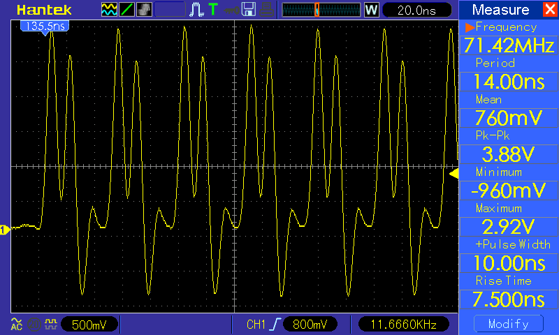
I thought it might be interesting to see how fast the processor can toggle GPIO lines, it has a neat feature where it has separate registers to set and clear values, this means a read-modify-write cycle isn’t needed to set bits, they can just be set in one operation. My oscilloscope only has 70MHz of bandwidth so it really struggled to see the GPIO lines toggle, when the speed of the signal is so close to the limitations of the scope I don’t really trust the results, all you really know is that the signal is very fast :) .
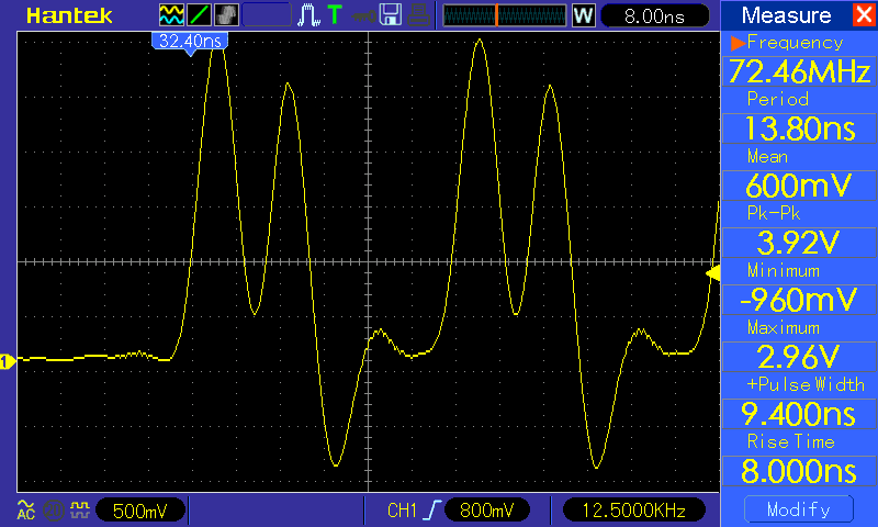
And here are a few more cycles captured: