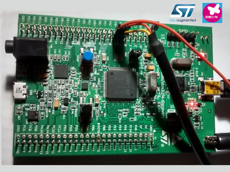
Here’s my first look at the DAC on the STM32 devboard (STM32 F4 Discovery).
The code for these examples can be found here.
Driving the DAC
The basic method
This first example is the most basic way of driving the dac, here is the code dac_basic.c. The code starts of by initialising the DAC, clock gpio, clock DAC and then enable channel 1 of the DAC. The main loop will then call the DAC loop (dac_basic_repeat()), this loop will simple increment the value that is stored in the DAC output register until it loops back to zero. Here is the output from the DAC observed on my oscilloscope.
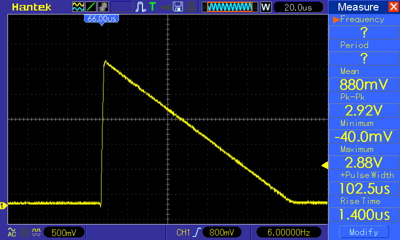
This is a good test of the DAC, but this wouldn’t be the best way of outputting a waveform on the DAC, it requires the ARM core to execute code continually to place in the output register. Another major problem is that it’s timing is completely dependent upon the ARM core, also if the core has to handle interrupts this will completely throw out the loop timing.
The DMA method
The best way to offload this work from the ARM core and have much better control over the timing of the output would be to use DMA. This method allows you to calculate a load of values to be output by the DAC and put them in a buffer, the buffer is then incrementally output to the DAC based off a trigger source, in this example a timer. The code for this example can be found in dac_dma.c.
The setup for the DAC is done in dac_dma_init(), it starts of by doing the same as the dac_basic example, then it enables a timer (timer6). A very useful feature of the DMA engine is that it can operate in circular mode, which means once it’s completed outputting a buffer it will start again at the beginning of the buffer, this means the main loop does nothing (apart from a bit of debug in this example). The code for this example is full of comments if you are interested in the details.
Waveforms in DMA mode
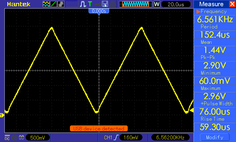
The waveforms appear to be a little clipped in these waveforms, I think this may be due to the DAC reference voltage, but it doesn’t really matter for the purpose of these examples.
The first waveform is a simple triangular wave, counts up and then down again.
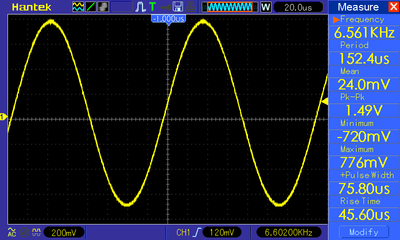
The second waveform is a sine wave, this is calculated using the sin() function that uses the FPU in the processor. The waveform is half scale and offset to avoid the clipping mentioned earlier.