Here are my first experiments with my new reflow oven setup.
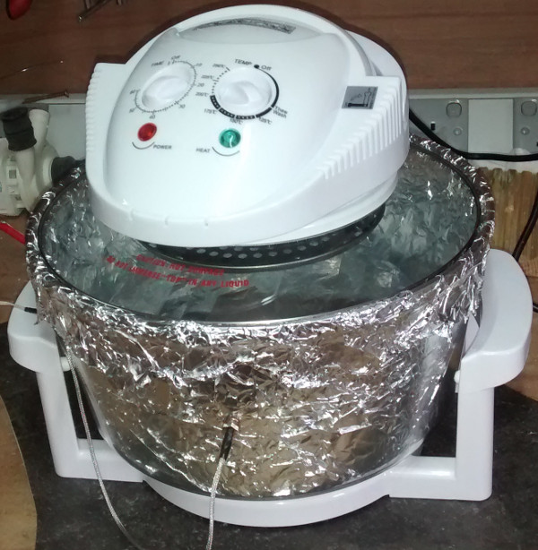
I want to build a reflow oven to aid with soldering surface mount components to PCBs. I found a great blog here on the subject. I’ve found the same halogen oven as the one used in the mentioned blog. I haven’t added any control to the system yet, I’m just testing to see if the oven can get up to temperature fast enough.
Before I ran the oven I made some modifications, I added some aluminium foil around the bowl (on the inside) and also bent the fan based on the advise in the blog.
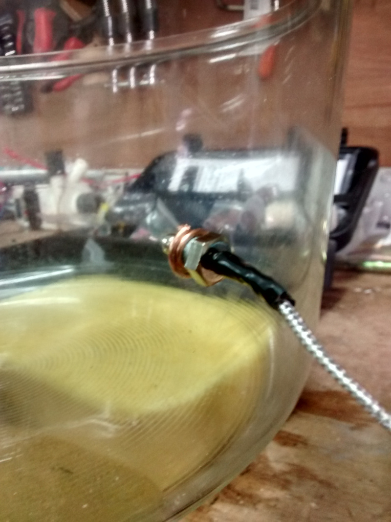
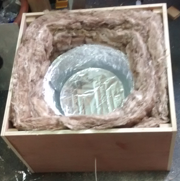
Here is where I cut the hole in the glass bowl for the thermocouple (notice how close it is to the outside of the bowl)
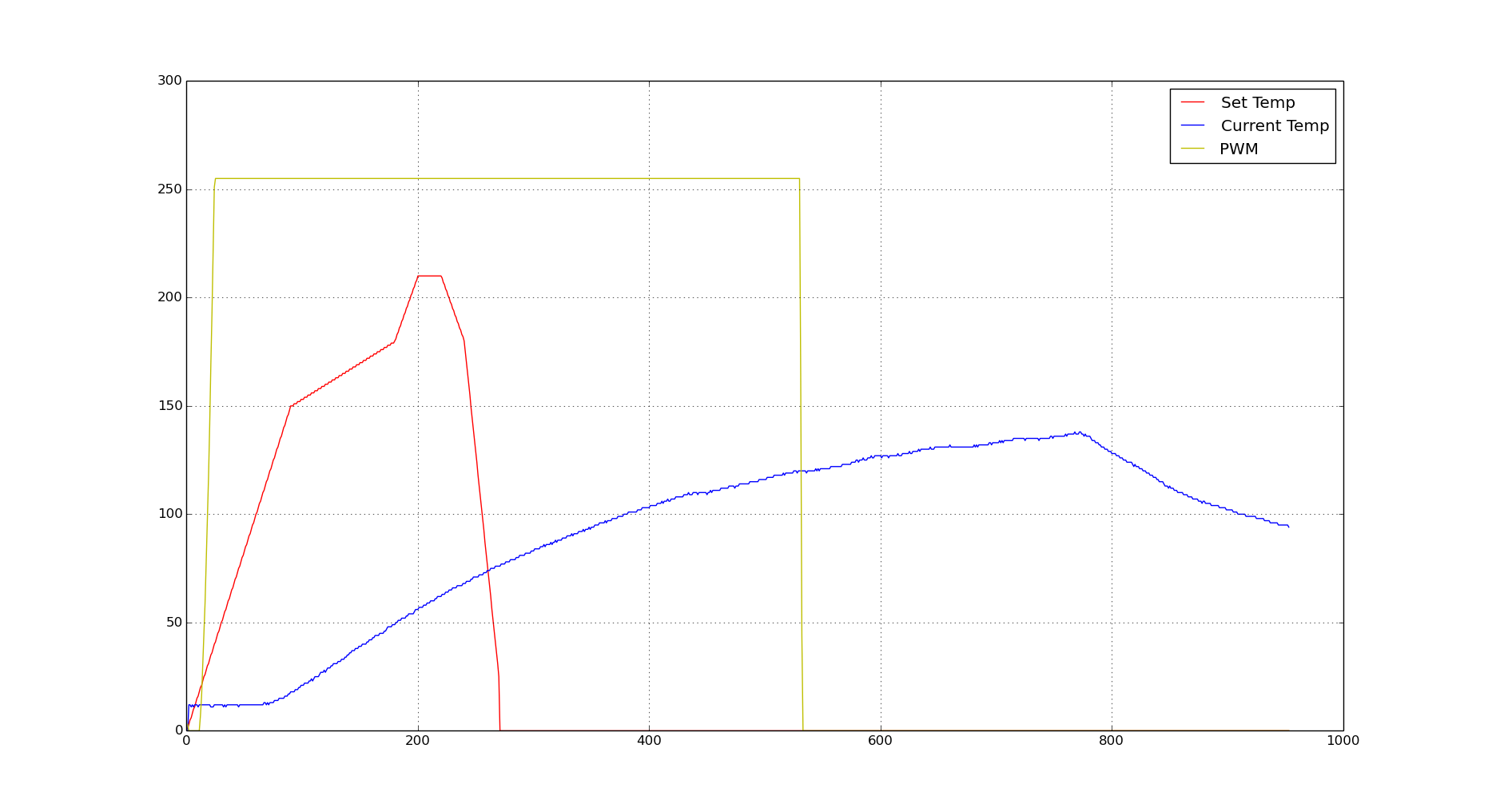
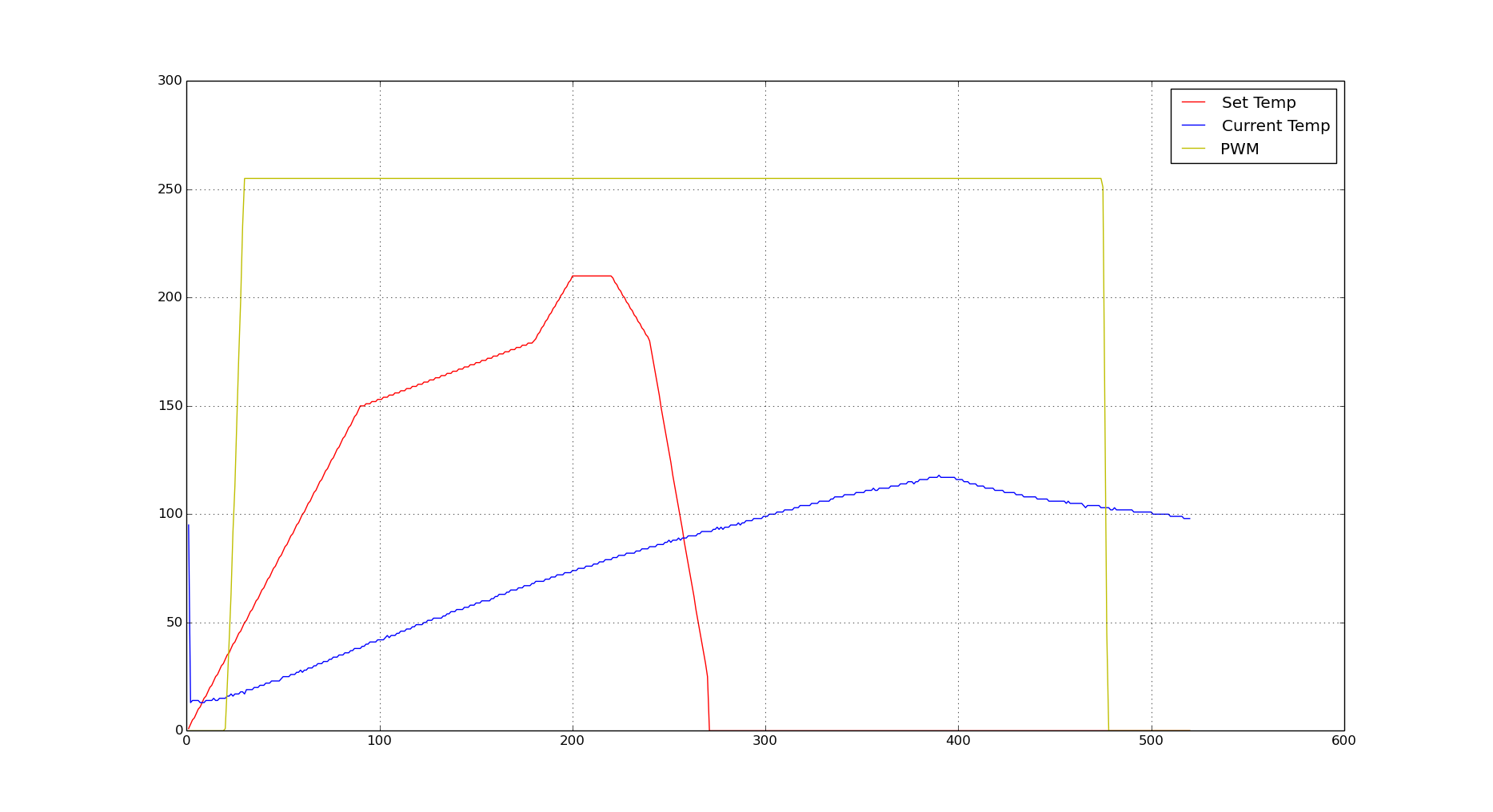
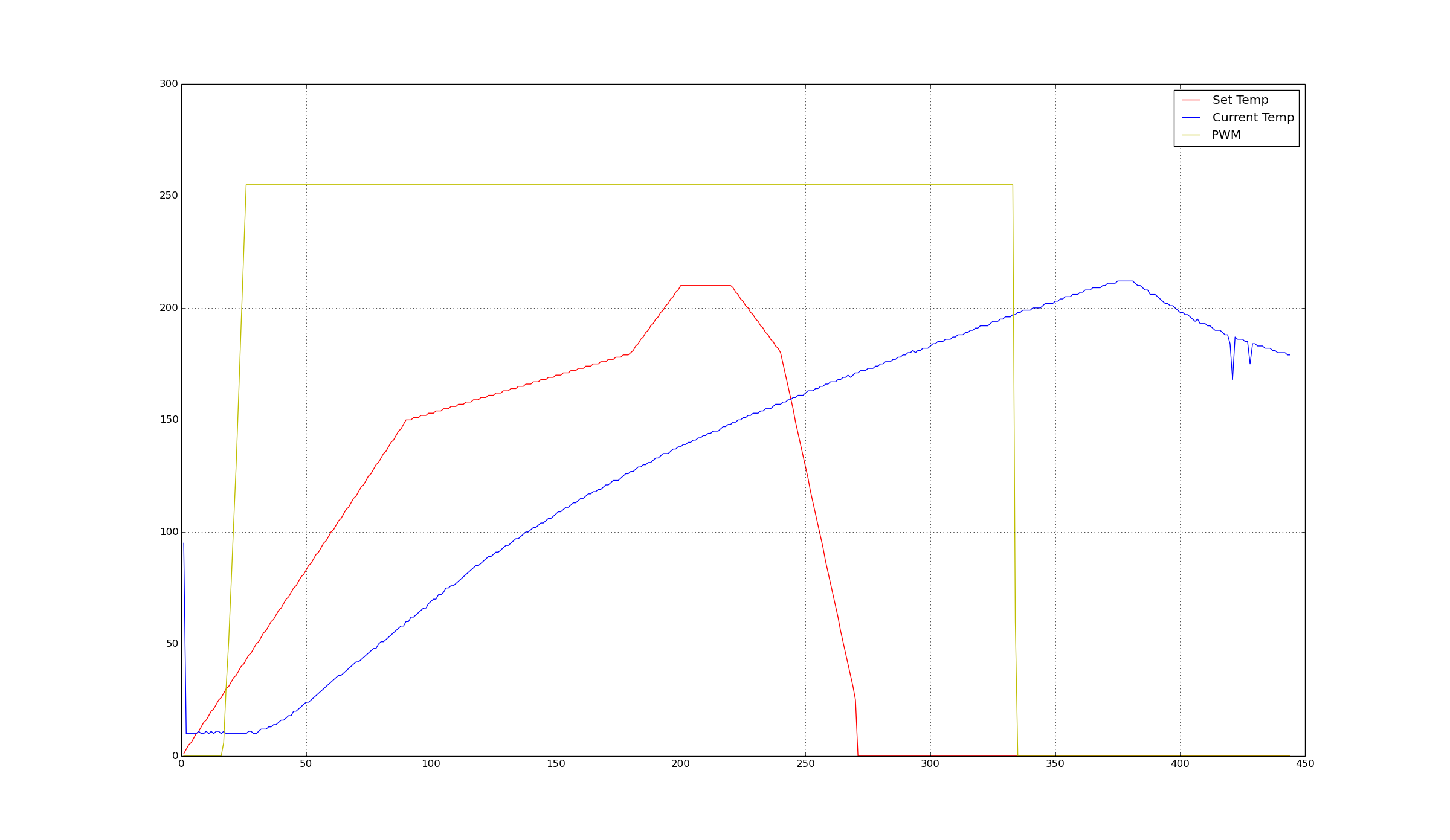
The following graph shows the results from the first run, they don’t look very good. The red line is the heat profile that we want to follow (for leaded solder), the blue is the temperature measured by the above mentioned thermocouple. The is with the halogen lamp fully on, these results show it can not get up to temperature fast enough.
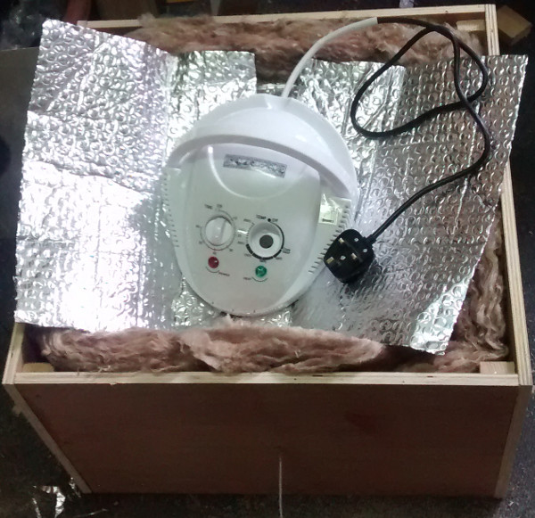
The garage was quite cold that day (about 10 deg C) so I thought perhaps the oven was loosing heat too quickly, I decided to make an insulated box for it with a bit of ply and some roofing insulation.
And a bit more insulation around the lid as the sharp drop off in temperature is only due to having the lamp turned off, not the lid being removed, I assumed there was a lot of loss through the lid.
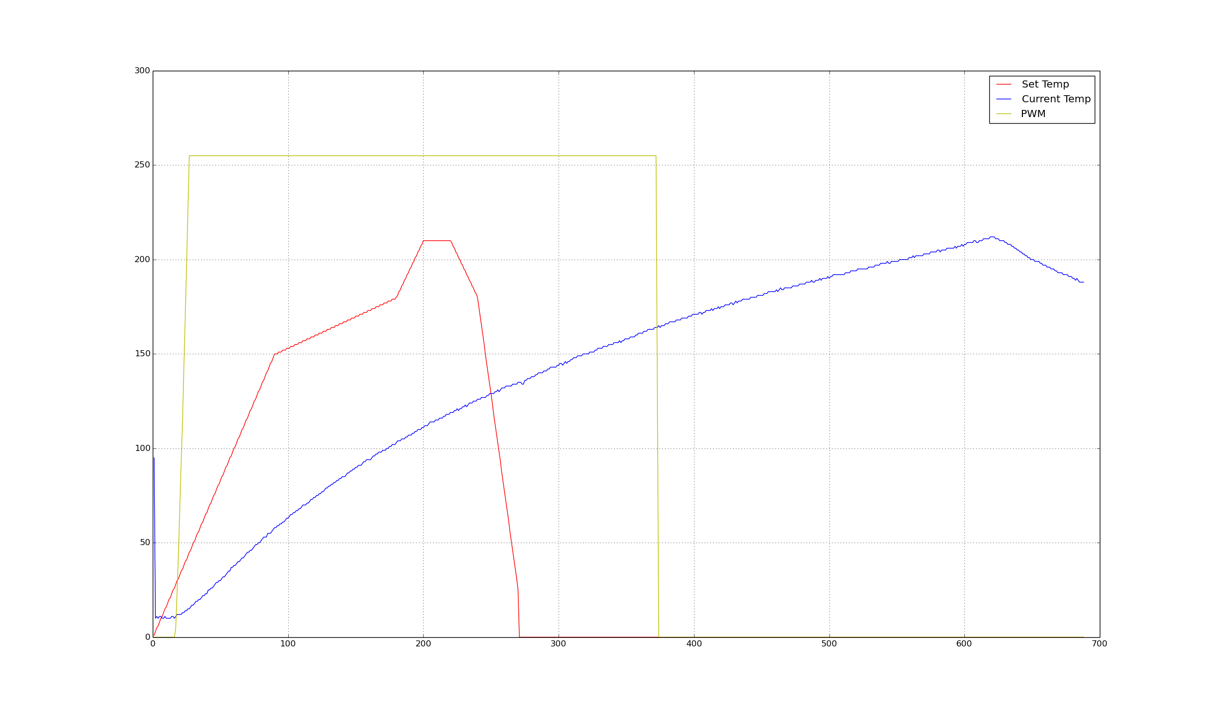
This did improve the results a bit
For the next run I added some sticky aluminium tape to the underside of the lid and removed the shelf in the oven to try and improve air flow.
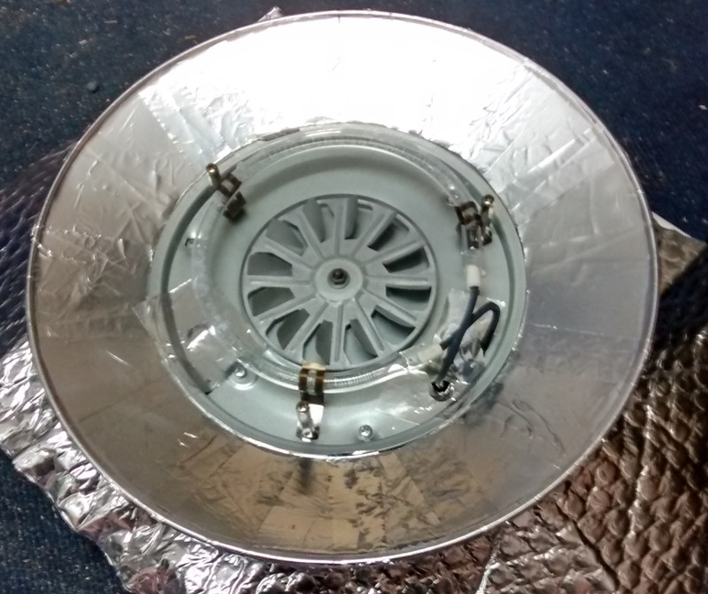
This time I removed the guard around the halogen element as I was sure that no food was going to touch the element :). Again these improvements did help a bit.
Here is a picture of the under side of the oven with the guard removed and the aluminium tape showing.
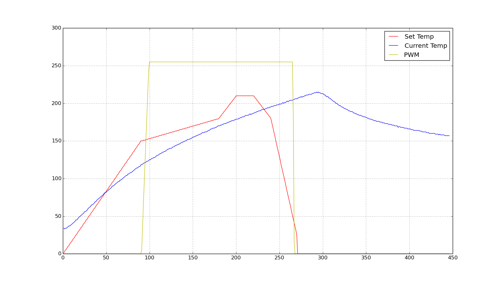
Here are some more results with some of the above modification, I think my notes of the experiements are a bit out of line with the data, never mind, you can see how things are progressing :)
At this point I was concerned the my results were extremely different to the ones show in the blog that i’ve been trying to reproduce. I decided to get a second temperature probe just in case my first one was giving incorrect readings or there were different temperature readings across the oven.
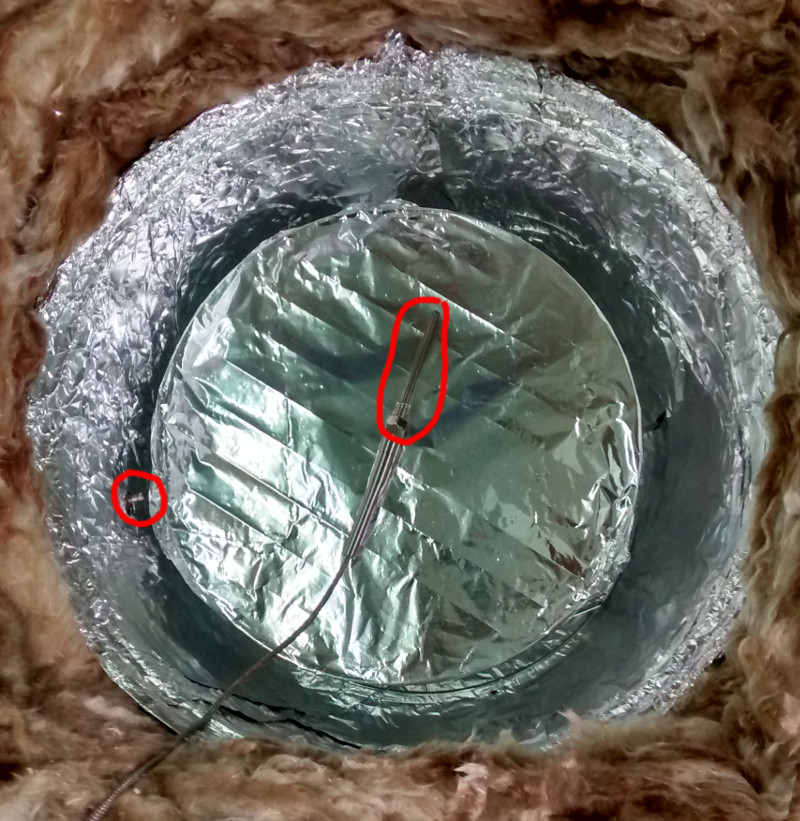
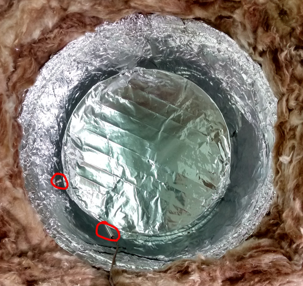
Here is a picture of the two probe setup, it’s worth noting that the probes are a bit different, they are both k-type thermocouples, but one has more metal around it.
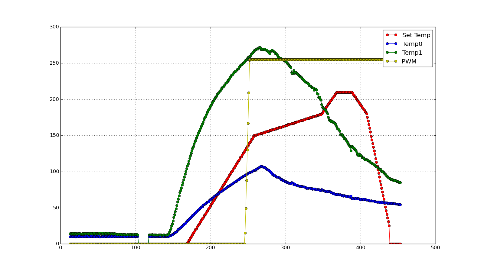
I warmed the garage up a bit before this run (about 5 deg C) but I don’t think it had much to do with the results. I was amazed by the new results.
The green line is the new probe and the blue is the old probe, they read almost the same temperature to start with until I turn the oven on, notice how much more quickly the new probes reading shoot up. These measurements exceed the required temperature ramp needed for the reflow profile i’m aiming for.
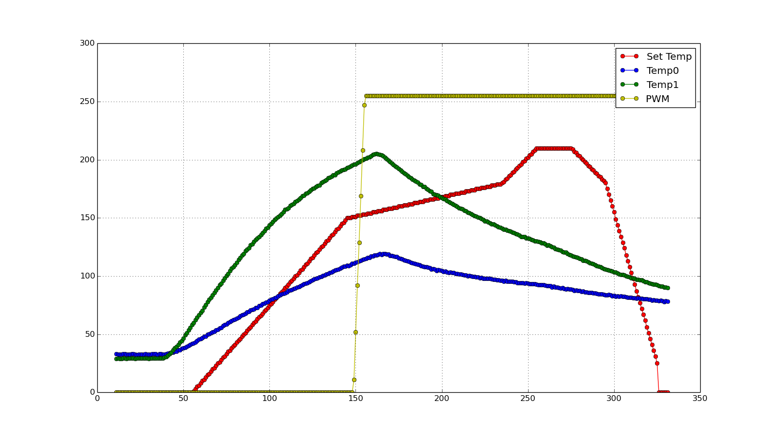
I wondered if this result was due to the second probe being place on top of the ovens shelf, so for the next run I places it under the shelf.
As you can see from the following data moving the probe did have some impact, but no much.
Conclusion
I think the results are so different due to the first thermocouple being thermally coupled to the glass side of the bowl which is why that temperature isn’t representative of the temperature that the PCB being reflowed would be exposed to. Now I just need to get the control working….
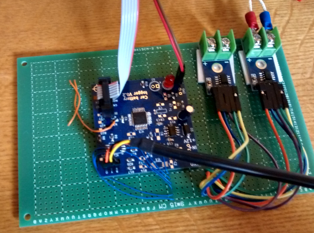
Circuit lash up
Here is the lash up I’ve been using to get the temperature reading shown above, it’s a board from a previous project and some MAX6675 chips from amazon (only £6 including the thermocouple). With the addition of a SSR (solid state relay) this should be enough to control the oven.