My first look at this really cheap Cortex-M0 development board.
Introduction
I was looking for a new cheap and low-ish power microcontroller and I found this Aliexpress dev board. It’s current only £0.98 per board, that’s pretty cheap and it has a Arm Cortex-M0 in it, it’s also available in packages that are quite easy to solder. The same chip is also available at farnell, so it shouldn’t be too hard to source them: Available at Farnell.
Source code
I like to start projects with the absolute minimum amount of code, I also prefer not to use IDE’s as I find them mostly just get in the way. I started this project by getting basic register definitions file from ST, creating a simple Makefile and from there created a program to exercise GPIO’s and the UART (print debug).
My code is available here
Start up code
The startup code consists of the following and mainly came from STM32Cube:
- Register definitions files.
- linker script.
- Startup assembler to configure the ‘C’ environment.
STM32Cube
I hand picked the required files from a file called ‘STM32Cube_FW_F0_V1.9.0’ from ST, available for download here STM32Cube.
Clock configuration
In the file ‘main.c’ (function init()) I configure the MCU clock to use the external 8MHz crystal and PLL to multiply it to 48MHz for the core.
Toolchain
The toolchain i’m using is GCC from Arm, i’m using this version gcc-arm-none-eabi-8-2018-q4-major-linux.tar.bz2.
My make file
My Make file requires two environment variables to be set:
- STLINK: This should point to a pre-built stlink tool (mentioned below).
- TOOL_BASE_GENERIC : The tool chain mentioned above.
This Makefile can be used to build the entire image and flash it to the target board. This makefile also has a couple of targets for disassembling the built binaries which is useful when debugging or if there are initial startup issues.
Programming
This board is very easy to program when you have the correct programmer and doesn’t require an extra bootloader stage.
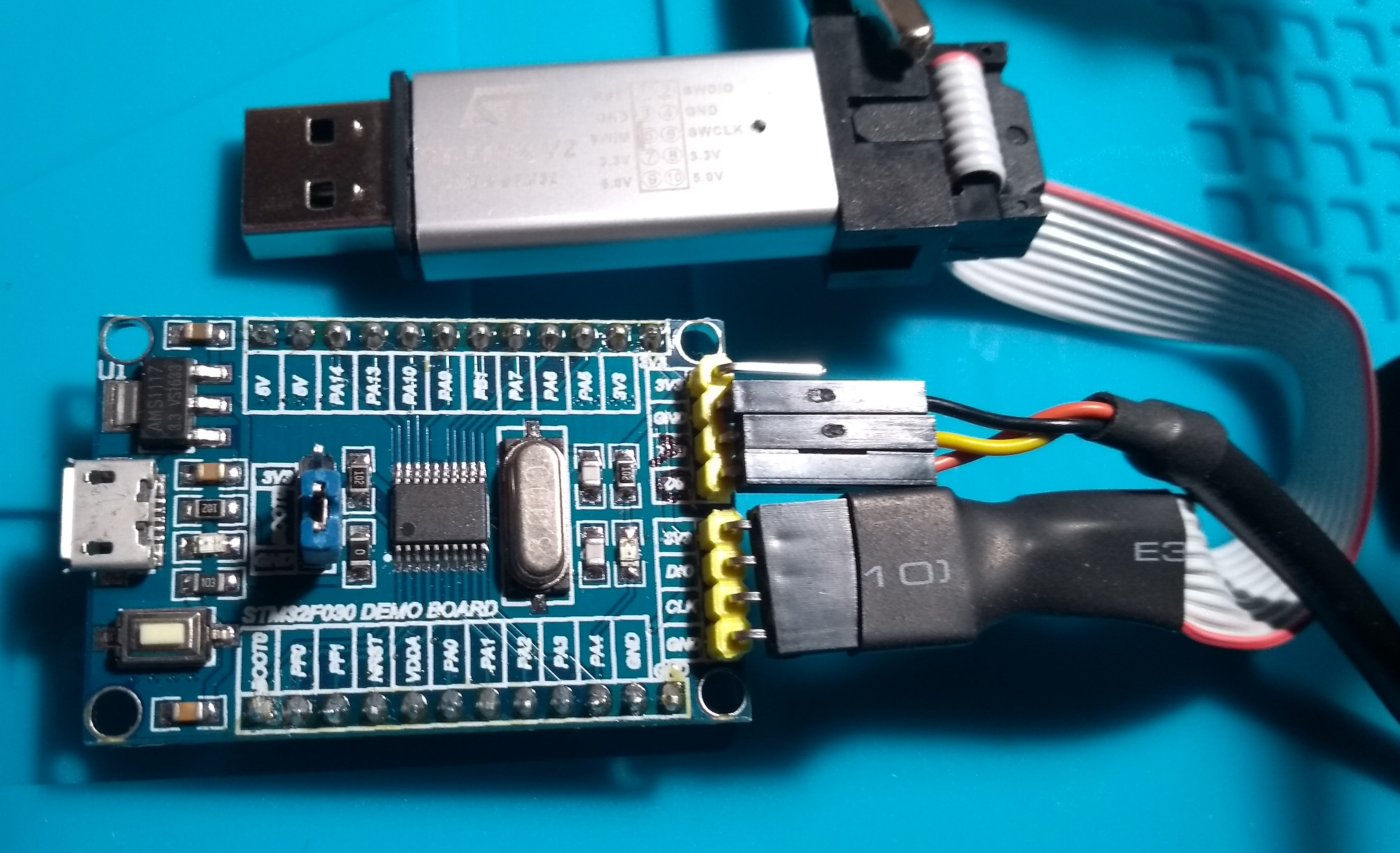
Hardware configuration
The hardware is setup as in the photo above, a ST-Link V2 programmer is connected to the SWD lines and an FTDI UART to USB cable it plugged in to see debug prints on the PC.
stlink
The programmer used is a ST-link V2, it also powers the board. To find this programmer search for “ST-Link V2 programmer” Aliexpress link It’s worth pointing out that I have several of these programmers and the pinout changes between models, so make sure you check the pinout before powering up.
This programmer requires some software on the PC to run, I use this Stlink tool, it works really well and I haven’t had any trouble with it.
Debugging
Even though this chip is really cheap it’s also possible to debug it using the hardware mentioned above and GDB running on the PC.
The connection to the device is created using stlink in one terminal as follows:
$> $STLINK/src/gdbserver/st-utilAnd the GDB session is started using the following command:
$> $TOOL_BASE_GENERIC/bin/arm-none-eabi-gdb -x ./gdbinit build/first.elf Conclusion
This chip has all of the peripheral you would expect in a modern microcontroller, it’s really cheap, easy to source, is easy to debug, available in easy to solder packages and did I mention it’s really cheap.